

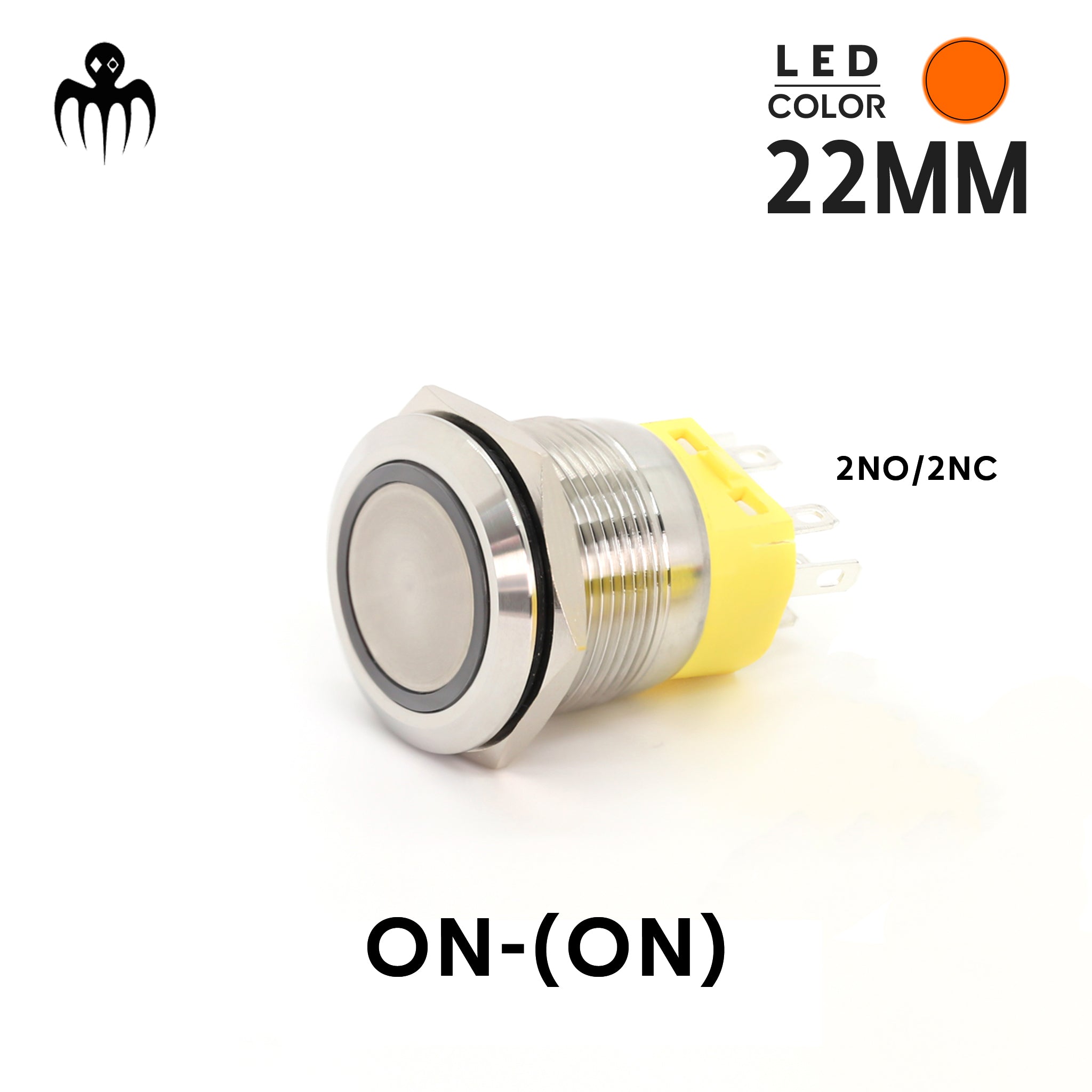




Changeover ON-(ON) Push Button | 2NO2NC - IP67
SKU:
PO22A
- 13.00€
- 13.00€
- Unit price
- per
22mm Momentary Changeover Push Button — 2NO2NC | IP67
- BAYWATT
- 22mm / 7/8"
- Momentary Changeover
- DPST 2NO + 2NC
- IP67
- 5A Max Contacts
- 12V Amber LED
- See Specs ↓
The BAYWATT PO22A is a 22mm momentary changeover push button designed for manual override, temporary bypass and control applications. It combines two normally-closed and two normally-open contacts in a compact panel-mount format, with an independent 12V amber LED ring.
At rest, the NC circuits are active. Press and hold the button to transfer the contacts to the NO circuits; release it and the switch immediately returns to NC. This behavior is commonly described as ON-(ON) or (ON)-ON.
How the Changeover Function Works
One button, two momentary circuit states.
- Released / default: NC1 + NC2 connected — the normal or automatic circuit remains active.
- Press & hold: NO1 + NO2 connected — the manual override or secondary circuit becomes active.
- Release: the switch automatically returns to the NC state.
5A contact limit: Loads within the switch rating can be controlled directly. For pumps, winches or other higher-current equipment, use the push button to control a correctly rated relay or contactor. The connected circuit must still be protected by the appropriate fuse or circuit breaker.
Why Use a Mechanical Changeover Push Button?
Changeover Logic Without a Relay Coil
Provides mechanical transfer between NC and NO circuits without coil wiring, standby current or relay buzzing.
Fewer Components
No relay socket or separate coil is required for low-current applications, reducing wiring and connection points.
Immediate Manual Control
Press to transfer the circuit and release to return automatically — ideal for temporary override or bypass functions.
Relay-Friendly for Higher Loads
Use the 5A contacts as a control signal for a relay or contactor when the connected equipment exceeds the switch rating.
Independent 12V Amber LED Ring
The LED circuit is independent from the changeover contacts, so the amber LED ring can be wired according to the indication you want on the panel.
Circuit Armed / Powered
Keep the LED illuminated whenever the controlled system is supplied, for a clear visual confirmation at the helm.
Manual Override Active
Wire the LED so it illuminates only while the button is pressed, providing immediate feedback that the override is engaged.
Typical Wiring Applications
1
Automatic Bilge Pump Override
Keep the automatic feed active through the NC path and use the NO path for a momentary manual override. A COM bridge can be used where the installation requires the same +12V supply on the override path.
- Released: automatic circuit remains active through NC
- Press & hold: manual override transfers to NO
- Suitable for 2-wire pump control logic
2
Temporary Disable / Service Control
Place the normal circuit on NC. While the button is held, NC opens and the function is temporarily disabled — useful for testing, servicing or preventing an automatic function from operating during maintenance.
3
Bypass / Reset Signal
Use the NO side to send a clean momentary command to a compatible reset input, alarm acknowledgement input, bypass circuit or control module.
Key Features
- DPST 2NO + 2NC contact configuration for changeover control logic
- Momentary operation: released = NC / press & hold = NO
- 22mm panel cut-out with Ø25mm bezel
- Stainless steel bezel with polymer rear body
- IP67 protection for demanding marine and vehicle installations
- 12V amber LED ring on an independent circuit
- 200mm pre-wired harness with connector and color-coded leads
Need help with an override circuit? Contact BAYWATT with your system voltage, load current and intended function.
PO22A Changeover Push Button — Technical Specifications
- BAYWATT
- PO22A
- 22mm / 7/8"
- DPST 2NO + 2NC
- IP67
- 12V Amber LED
- Product Overview ↑
| Parameter | Specification | Notes |
|---|---|---|
| Model | PO22A | BAYWATT momentary changeover push button |
| Mounting Hole | Ø22mm / 7/8" | Standard panel cut-out |
| Bezel Diameter | Ø25mm | Stainless steel front bezel |
| Maximum Panel Thickness | 12mm | Maximum supported panel thickness |
| Switch Function | Momentary changeover — ON-(ON) | Released = NC / Press & hold = NO |
| Contact Configuration | DPST — 2NO + 2NC | Two NO and two NC contacts |
| Contact Rating | 5A max (DC) | Use a relay or contactor for higher-current loads |
| LED Ring | Amber — 12V DC | Independent LED circuit |
| Ingress Protection | IP67 | Protected against dust and temporary water immersion |
| Housing | Stainless steel bezel + polymer body | Panel-mount construction |
| Wiring | 200mm pre-wired harness with connector | Color-coded leads |
| Electrical Life | 50,000+ cycles | Product specification |
Operating logic: with the button released, the NC contacts are closed. Press and hold to open the NC contacts and close the NO contacts. Releasing the button returns the switch automatically to NC.
Installation requirement: The 5A switch rating does not replace circuit protection. Use the correct fuse or circuit breaker for the connected load and cable size, and use a suitably rated relay or contactor when the load exceeds the switch contact rating.
For wiring assistance, contact BAYWATT with your application details.
How to use :
Link to the blog
Discover tips, tricks, and detailed instructions on using our product in our dedicated blog post. Learn about setup, operation, and optimization to get the most out of your purchase.
Link to the blog
Our Recommendations


22mm RBG LED Push Putton 12V 5A - Latching/Momentary - Marine IP65
- 9.00€
- 9.00€
- Unit price
- per


Dimmer Button 22mm 12/24V 5A - Waterproof IP67 - White or Blue LED
- 21.00€
- 21.00€
- Unit price
- per


12V RGB Push Button Switch 22mm Vandal-Proof IP67
- 16.00€
- 16.00€
- Unit price
- per


Curved Face Buzzer Alarm IP67 - 12V/24V - 22mm
- 12.00€
- 12.00€
- Unit price
- per


Waterproof LED Buzzer Alarm IP67 - 12V - 22mm
- 10.20€
- 10.20€
- Unit price
- per
- Choosing a selection results in a full page refresh.


