



ATR1224 - Universal multi-timer relay
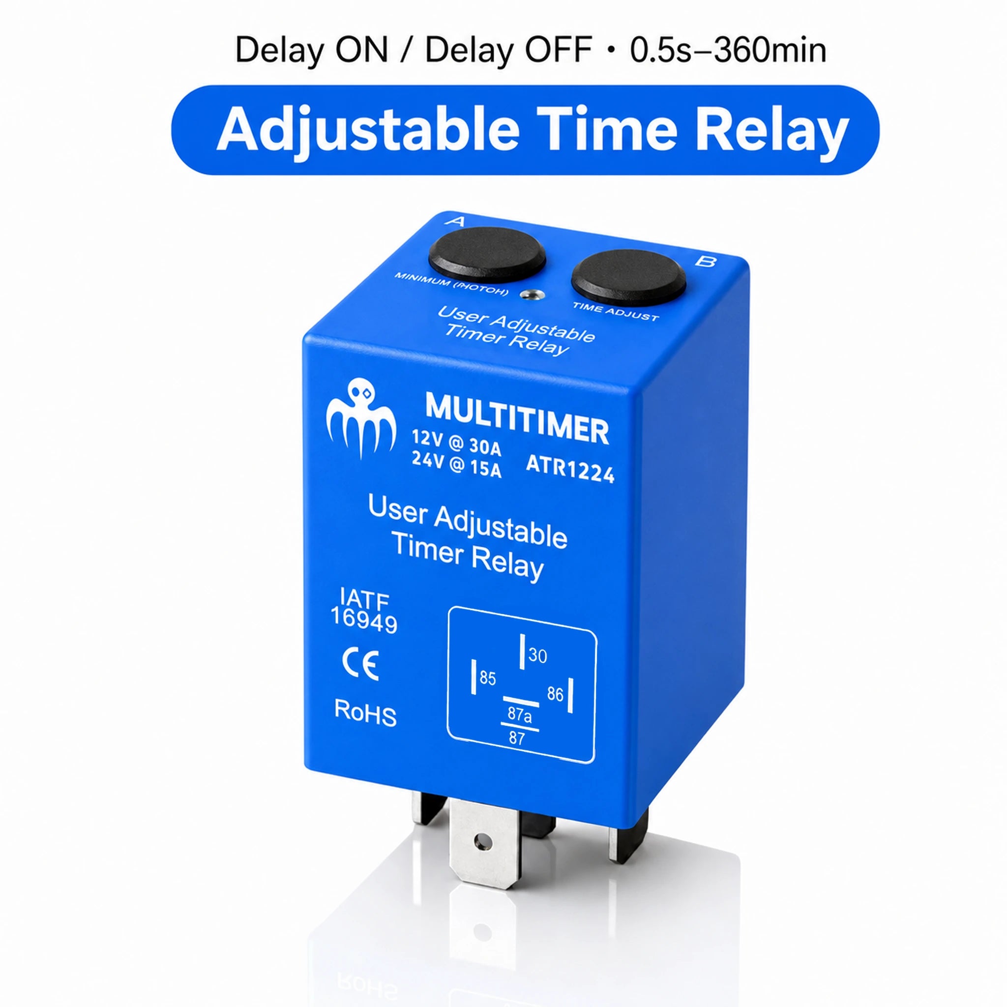
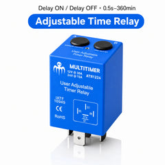
12/24V Adjustable Timer Relay - Delay ON / Delay OFF - 30A at 12V
One compact adjustable timer relay for 12V and 24V DC systems. Set Delay ON or Delay OFF from 0.5 seconds to 6 hours. Rated up to 30A at 12V and 15A at 24V.
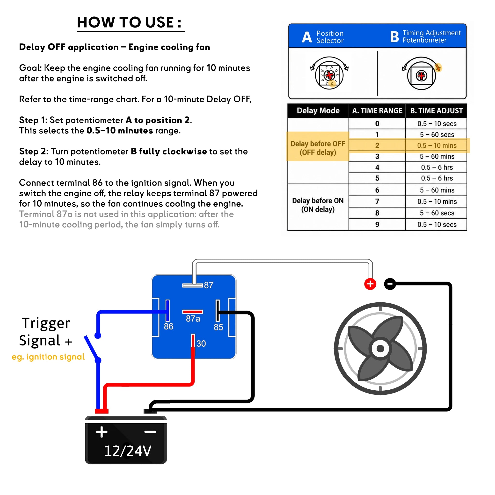
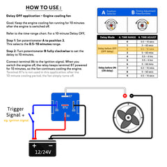
How to set a 10-minute Delay OFF

Simple set-up
1. Set A to position 2. This selects Delay OFF with a 0.5-10 minute range.
2. Turn B fully clockwise. This sets the delay to approximately 10 minutes.
3. Wire the fan to terminal 87. Connect terminal 30 to a permanent fused positive supply, 85 to ground and 86 to the ignition-switched positive signal.
When ignition is switched off, the fan stays powered for the selected 10 minutes, then turns off automatically. Terminal 87a is unused in this application.
What is it?
BAYWATT ATR1224 is a 12/24V adjustable timer relay in a compact 5-pin SPDT automotive relay format. It combines a high-current changeover relay with an adjustable electronic timer, so you can customize how long a circuit waits before switching on or how long it remains powered after its trigger is removed.
This is one bi-voltage 12/24V timer relay, not separate 12V and 24V references. Its switching capacity is clearly rated at 30A at 12V or 15A at 24V.
How does the adjustable timer work?
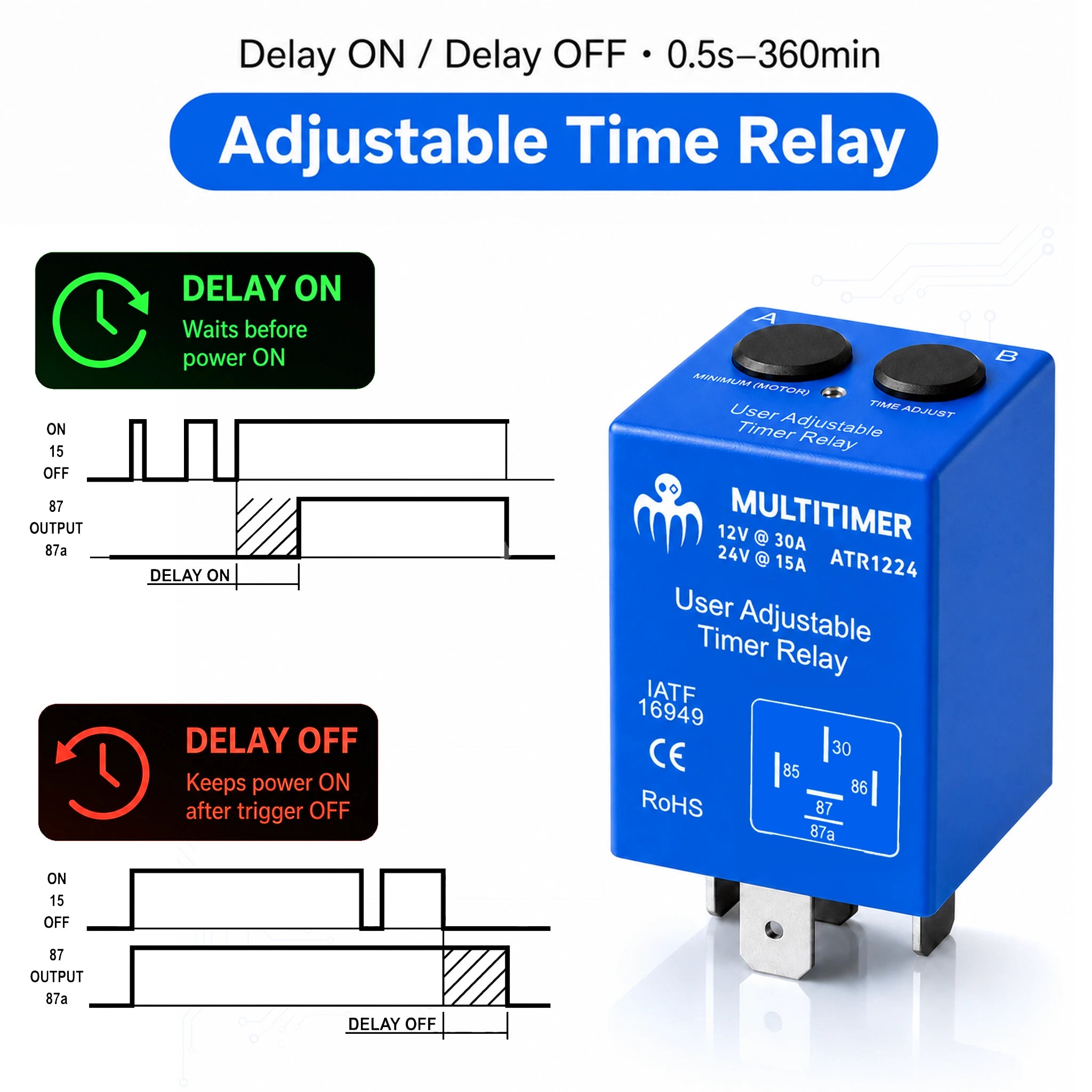
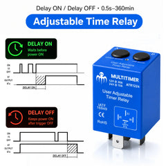
Delay OFF: power stays ON after trigger OFF
When terminal 86 receives a positive trigger, terminal 87 powers the load immediately. When the trigger disappears, the selected timer begins. Terminal 87 stays powered, then switches off at the end of the delay.
Trigger ON - 87 ON - trigger OFF - selected delay - 87 OFF
Delay ON: wait before power turns ON
When terminal 86 receives a positive trigger, the timer starts. Terminal 87 remains off during the selected delay, then powers the load when the timer ends.
Trigger ON - selected delay - 87 ON
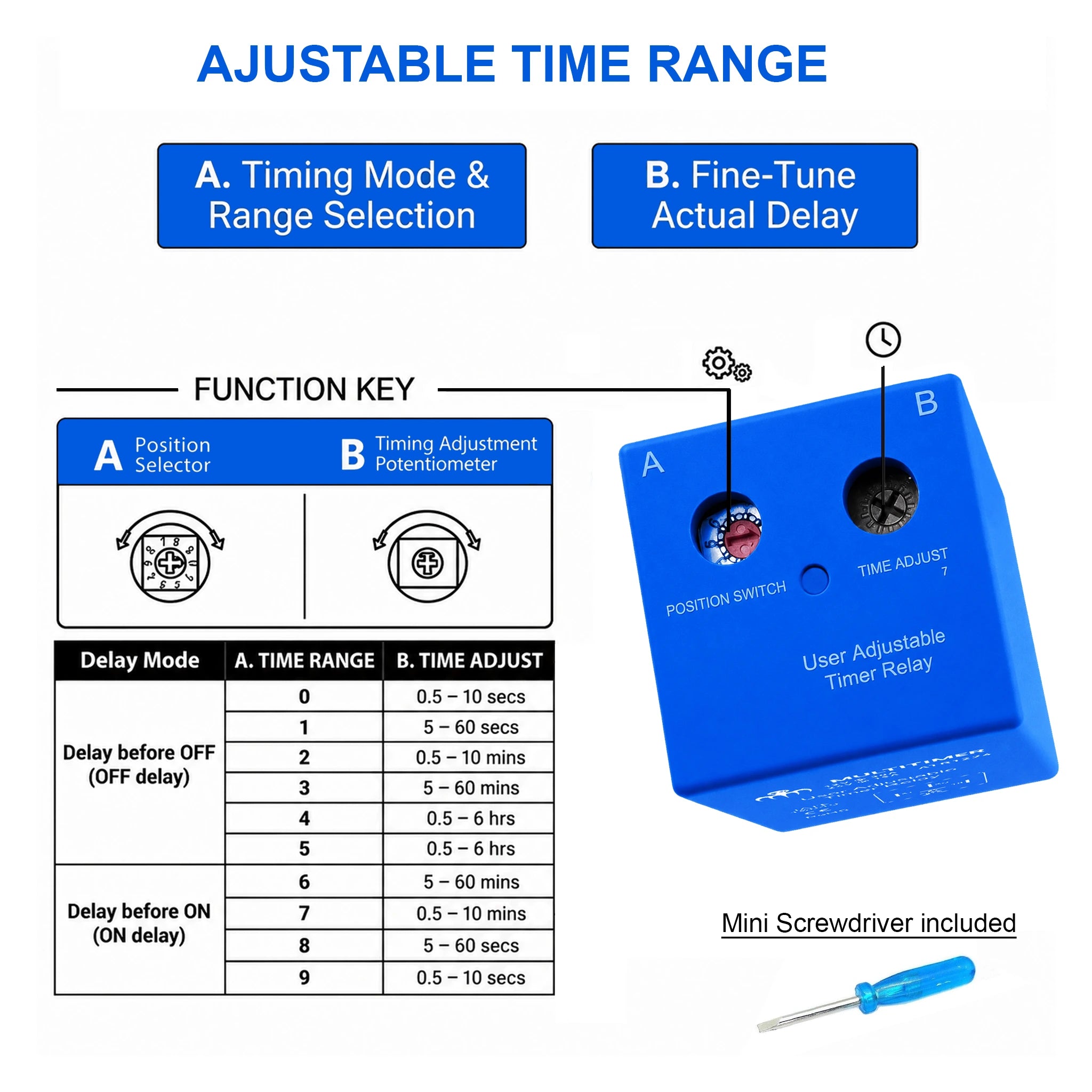
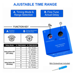
A. Time Range / B. Time Adjust
A selects the mode and broad time range. B adjusts the exact time within that range. Turn B counter-clockwise for the shortest delay and clockwise for the longest delay.
| Delay mode | A. Time range | B. Time adjust |
|---|---|---|
| Delay OFF Output switches OFF after the trigger is removed |
0 | 0.5 - 10 seconds |
| 1 | 5 - 60 seconds | |
| 2 | 0.5 - 10 minutes | |
| 3 | 5 - 60 minutes | |
| 4 | 0.5 - 6 hours | |
| Delay ON Output switches ON after the trigger is applied |
5 | 0.5 - 6 hours |
| 6 | 5 - 60 minutes | |
| 7 | 0.5 - 10 minutes | |
| 8 | 5 - 60 seconds | |
| 9 | 0.5 - 10 seconds |
5-pin timer relay wiring diagram
Use conventional automotive relay terminals. Terminal 30 is the permanent fused positive supply, 85 is ground, 86 is the positive trigger, 87 is the normally open timed output, and 87a is the normally closed alternate output.

Applications
Customize your own timer instead of using a fixed-delay relay. The ATR1224 suits boats, vans, RVs, 4x4s, trucks, agricultural machines and auxiliary DC equipment.
- Engine cooling fans and ventilation blowers
- Delayed instrument or accessory activation after ignition
- Cabin, cockpit, deck and courtesy lights
- Fresh-water, circulation and washdown pumps
- Solenoid valves, compressors and auxiliary motors
- Sequential start-up to reduce peak current draw
- Control signal for a separate high-current relay or contactor
Mini screwdriver included: adjust gently
A mini flat screwdriver is included to reach the recessed A and B adjustments. Use the supplied screwdriver or a very thin flat blade.
- Do not push hard on the potentiometer; turn it with light pressure only.
- Do not use a large screwdriver or a wide blade.
- When B reaches the end of its travel, stop. Never force it.
- Set A first, then set B and test the timer before final installation.


